
Month: November 2017
Z06 Camaro
Gen V LT1/LT4 header collector gasket and flange
by desmodave •
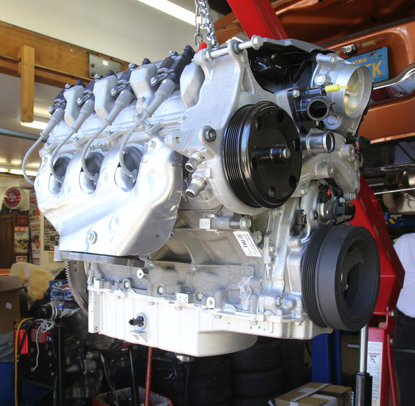
When I was making up my collector flange for the exhaust system, we designed a template that acted as both the design for the gasket and the flange itself. I searched high and low, but was unable to find anything available off the shelf other than direct from GM, this is a unique flange/bolt arrangement that appears to be only used on the GEN V engine. GM wants $57.00 for a gasket and almost $600 for each downpipe that connects to the header, so here’s a simple solution.

This is the header system that the template will fit, click on the image for a higher resolution view.
Collector template -download this PDF file for fabrication.

This template is scanned full size on a regular sheet of paper so when you print it out, please print actual size so the image doesn’t get distorted. The actual diagonal distance between bolt holes is about 3 7/8″. The pipe diameter is 2 1/2″, but we elected to design the flange so the exhaust tubing entered into the hole rather than be welded on the outside, for thickness we used 5/16″ thick steel. It’s your choice, but adjust the diameter of the exhaust hole based upon the size of the exhaust tubing your’e using.
For the gasket we used aluminum and heat tempered it so it was pliable, worked great and saved a ton of money.
Uncategorized
GEN V LT1/LT4 VSS and tach signal generation
by desmodave •
I’ve had quite a few inquires lately in regards to how to power and drive your conventional mechanical or electronic speedometer from the new GM 8L90E 8-speed transmission. After talking at length with GM Performance and Powertrain they have provided a few solutions that should work.

The 8L90E transmission is a second-generation model that uses an electronic controller built within the transmission itself. If you’re using the GM “Connect and Cruise” system it includes a separate controller (black rectangle with blue connector above right) that communicates back and forth between the engine ECU and the transmission itself. This system is part of the CANBUS or GMLAN electronic control system and is for all practical purposes standalone, they don’t want you piggybacking off the system because you can potentially disrupt the network transmission protocol. For the 8 speed automatic transmissions, the vehicle speed information is fed to the transmission controller through a pulse signal. The Vehicle Speed Sensor connector (on the wiring harness) is not used because there isn’t one on the 8L90E to plug into (see below). The ECM is programmed and looking for 40 pulses per revolution.
I have successfully piggybacked off the VSS signal from a T56 manual transmission and generated the correct speed using the Dakota Digital VHX gauge package with their BIM 01-2 module. Using the VSS signal from an ECM requires a single wire input into the Dakota Digital bus. Since the signal is generated outside the GMLAN, a simple pulse generated inductive signal from a magnet, I believe it doesn’t disrupt the signal going to the ECM (see my LT1/LT4 installation guide for more guidance). This is necessary because both the LT1 and LT4 Gen V engines require a VSS signal, without one they go into ‘limp mode’ and run at 1/3 throttle. Set up this way my engine and transmission function correctly because they do not generate any check engine codes or MIL lights.
GM Powertrain recently brought to my attention that pin 14 (grey/blue wire) out of the transmission will provide a non-CANBUS raw signal (pulse generated) that should drive a conventional electronic speedometer. This is an inductive type signal so voltage output is dependent on speed.

This is the plug that connects to the 8L90E transmission, if you look closely you can see the grey wire.
The plug goes into the transmission here.


One simple solution available is a conventional shaft mounted VSS signal generator like this:
Summit Racing sells this part: https://www.summitracing.com/parts/dak-sen4165/overview/. This is a VSS magnet kit with pick up coil. Normal rear wheel drive domestic installation takes four magnets on the drive shaft with a pickup coil mounted approx 5/8″ away. It seems odd that you would use old school mechanical magnets spinning around on the outside of your driveshaft to get a signal that your speedometer can read, but it’s a least a solution.

A little bit more elegant solution is this split-collar speed-sensor that is used on data-acquisition systems
Another option is a GPS driven signal like this:

The best solution seems to be the recently released STA-100 ODBII interface that not only handles the speedometer issue, but also provides a tachometer signal. There is also pin C (white wire) output from the bulkhead connector on the GM wiring harness that provides engine speed, but it’s a CANBUS signal and will not drive an aftermarket electronic tachometer unless it’s OEM.

The STA-1000 plugs directly into the OBDII diagnostic connector, providing a user-adjustable traditional Speedometer, Tachometer and Check-Engine output for your choice of aftermarket instruments.
Features:
- Fully compatible with common aftermarket electronic speedometers
- User selectable output of: 4k, 8k, 16k PPM signals, Sine or Square wave options
- +/- 35 percent speed signal correction, compensating for tire size or gearing changes
- Adjustable 4, 6 or 8 cylinder tachometer signal output
- Check Engine light output provides a grounded (-) output to activate a check engine light of your choice
- Automatically calibrated output for an aftermarket cruise control can be activated by making connection to the higher-resolution fixed VSS sensor
- Small footprint measures 4-3/4″x 3″x 1″ making it easy to hide
- Compatible with J1850 and CAN OBDII protocols
Stay tuned for more….

Uncategorized
Gen V LT1/8 speed “Connect and Cruise” install on a ’55 Chevy 2 door post
by desmodave •
I have made a wee bit of progress, the two steps forward part. Motor is in, small amount of cutting and grinding and welding…well, ok, a lot of that. Note I cut off a bit of the motor mount to have access to the oil port for my oil pressure gauge. Put on the Drive Junky belt system today. Found out that I can use a rack and pinion steering which takes care of the header clearance problem.
The fuel tank is ready to be TIG welded (Rick’s Tanks). However the 500 # gorilla is still in the room, that’s the 8 speed, and yes, you are right, 1st gear is like 4.56, I found out that the rear end is 2.20:1. Not sure if that is within the parameters of the ECM, might have to swap gears later. I have to get the steering in before I can move the car back over to the lift side and slide the tranny under the car. Then I can see how much of the 60 year old floor I have to cut away. Anyway it is some progress. – Harry Abbott, Oak Harbor, Wa.

Latest photo from Harry -12/5/2017


DriveJunky serpentine system


Rick’s tank bung to be welded into Tank’s Inc FI tank


Dirty Dingo engine mounting plates adapted to frame
